Lorem ipsum dolor sit amet, consectetur adipiscing elit. Fusce fringilla fermentum leo, non posuere ex fermentum ut. Mauris convallis mauris at dictum consequat.
Ceci est la description complète de mon block
LEMは新しいブランドアイデンティティを明らかにします
- LEM New Identity
-

- LEM New Identity
-

Ma description

Test 1234 Body
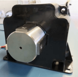
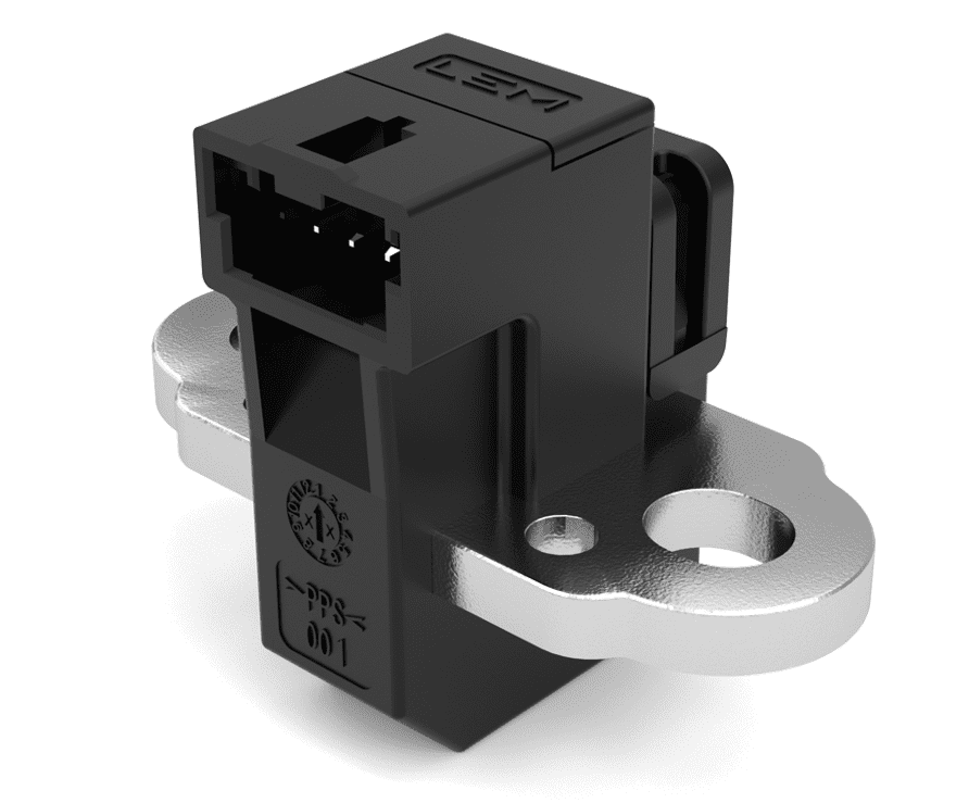
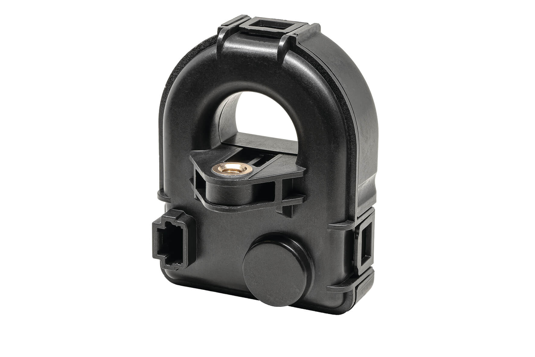
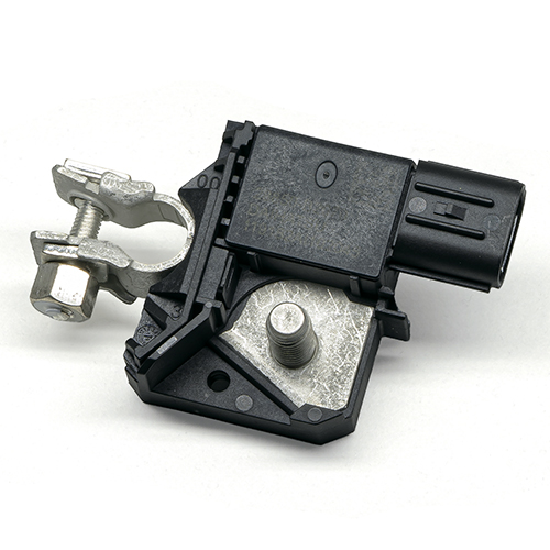
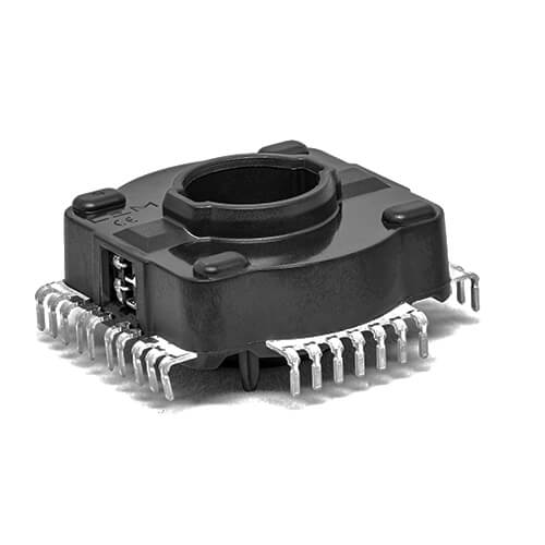
Mon block Text + Image

Fusce tincidunt quam sed odio egestas, ac dapibus erat tempus. Donec tortor justo, porttitor id massa sed, tempus efficitur sem. Nullam tincidunt tellus eu ex ullamcorper, sit amet feugiat odio elementum. Vivamus vulputate at augue ut consectetur. Phasellus tempor fringilla luctus. Nulla ut nunc risus. Phasellus ullamcorper dui eros, ac convallis lorem tincidunt eu. In lectus tortor, rutrum quis lacinia id, aliquet quis felis. Phasellus fringilla justo justo, ut gravida tortor ullamcorper id. Fusce laoreet est vitae ligula euismod consectetur. Donec sodales orci ac nunc finibus fermentum. Aliquam erat volutpat. In ac posuere odio.
マイ・ビデオ
FAQs
-
Which parameters must be considered when choosing a transducer?
Take into account all aspects of the application
All aspects of an application must be taken into account for the selection of the transducer and system design, with particular attention to the following:
- Electrical requirements, including power supply requirements, peak measurement, response time, di/dt and dv/dt.
- Mechanical requirements, including aperture size, overall dimensions, mass, materials, mounting and vibration.
- Thermal conditions, including current profile versus time, maximum RMS measurement, thermal resistances and cooling.
- Environmental conditions, including vibration, operating temperature range and proximity of other conductors or magnetic fields.
Identify potentially critical elements
Some applications have a higher level of complexity and combine several potentially critical elements such as:
- electromagnetic interference
- significant common mode voltage transients (dv/dt)
- mechanical disturbances (vibration, shock, etc.)
- special isolation or partial discharge requirements
- compliance with specific standards, etc.
Perform tests
Obviously the best scenario is to perform tests in the specific application environment. If this is not feasible, please provide LEM with a diagram of your installation and a detailed description of the transducer operating conditions (e.g. description of the environmental conditions, graph of the waveforms to be measured, nearby potentially disturbing elements such as inductors, current carrying conductors and the presence of magnetic materials or the location of other transducers).
-
How is “primary nominal” rms current or voltage determined?
Sometimes also called “continuous or rated” current (voltage), it is the maximum permanent thermal current (voltage) that the transducer can carry.
Another definition is: the maximum rms current (voltage) which may flow through the transducer under specific conditions, so that the temperature during continuous operation does not exceed the specified value. This is measured with a 50Hz sinusoidal signal.
-
What does “measuring range” imply?
The measuring region is limited by the maximum measurable peak value in non-steady state.
- Example for closed loop transducers including those based on fluxgate:
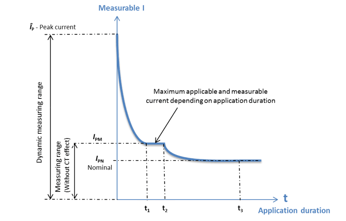
The transducer can, in fact, measure much higher current values, provided the duration of this current is very brief and non-repetitive. This is then called the dynamic measuring range which is limited by the peak current. In this case, the transducer operates as a current transformer (CT effect).
The maximum peak current will depend on the load (measuring) resistance, bus bar temperature and transducer’s construction. The dynamic range and the admissible duration times (t1…t3) are not determined and are not indicated in the data sheets because of multiple parameters that can interact.
- For an open loop hall effect transducer
The measuring range will be linked to the saturation of magnetic circuit or the limit of the voltage output stage.
- Example for closed loop transducers including those based on fluxgate:
-
What is the function of the measuring, burden or load resistor (RM, RB)?
Voltage sensors and current sensors giving a current output need to have a burden resistor (RB or RM - also called measuring or load resistor) connected to their output in order to obtain the correct measurement.
Closed-loop sensors have an integrated current generator that supplies the output signal. The burden resistor is set to define the best current/ to voltage ratio for your application. Current signals are also much less sensitive to external perturbation, which is important when there is larger distance between the location of the sensor and the control electronics processing its signal.
-
What are the limits of measuring resistor (RM, RB)?
The measuring resistor has to be within a defined range to allow a safe and optimum operation of the transducer.
- The minimum resistor value is set for thermal protection of the output power stage of the transducer. This can be 0 Ω for some transducer types (the maximum power supply voltage will be determining for the calculation).
- The maximum resistor value is set to allow a defined current / voltage measurement range for the transducer. It corresponds to the resistor which will not lead to the electrical saturation. Connecting a higher resistor than the one specified will reduce the measurement range of the transducer (min. power supply voltage will be determining for the calculation).
In case you need values out of the range specified on the datasheet of the transducer, please contact your technical support. Different values can be computed depending on your application conditions (ambient temperature, power supply voltage tolerances and maximum current/voltage to be measured).
-
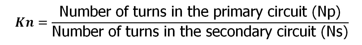
What is the transformation ratio?
The rated transformation ratio K is the ratio of the rated primary voltage or current to the rated secondary voltage or current. For closed loop current transducers, the turns ratio NP/NS is approximately the reciprocal of KR. For example, a turns ratio of 1:1000 implies approximately 1000 secondary turns (KR = 1000) and a secondary current of 1mA with a single primary turn carrying 1A.
-
What is the current consumption IC ?
It is the maximum current consumption of transducer’s electronics at the specified supply voltage when the primary signal is nil, added to the secondary current IS . This parameter is applicable only to the transducers with current output.
-
How should the power supply for a transducer be dimensioned?
Only transducers using the closed loop technology require special care when defining the power supply and its limitations. Due to the working principle of closed loop current and voltage transducers, the current consumption IC can be spit in two parts: a fixed one at primary nil plus the part which is the function of the current/voltage to be measured (IS). The second part can be calculated as follows:
- For a current transducer: IS = peak primary current x turn ratio
- For a voltage transducer: IS = (peak primary voltage/primary resistor) x turn ratio
-
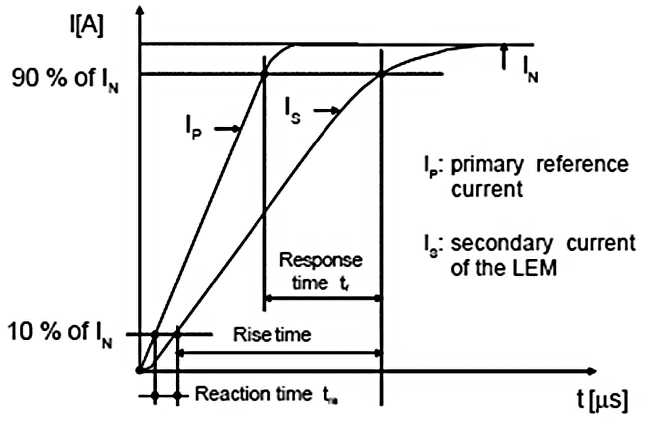
How is the response time (tr) defined?
Used to characterize dynamic behavior of a transducer, step response time is the delay between the primary current reaching 90% of its final value and the transducer’s output reaching 90% of its final amplitude. The primary current shall behave as a current step, with a given di/dt slope (usually 100A/µs) and with the amplitude close to the nominal current value IPN .
-
How is the reaction time (tra) defined?
LEM defines the reaction time (tra) as the delay between the rise time of the output signal and the rise time of the applied signal taken at 10% of the total variation of IPN .
-
What does “di/dt accurately followed” mean?
Used to characterize dynamic behavior of a transducer and its ability to follow fast changes in primary current, “di/dt accurately followed” is the variation of primary current for which the response time does not exceed 1 ms at 90% of IPN.
-
How is the frequency bandwidth BW defined?
The bandwidth is the frequency comprised between 0 Hz and the cut-off frequency corresponding to an attenuation of 3dB , unless otherwise specified. It is the measure how rapidly the amplitude and phase of the signal fluctuate with respect to time. Hence, the greater the bandwidth, the faster the variation in the signal parameters may be.
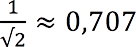
The attenuation of 3dB corresponds to the half-power decrease or the decrease of the signal amplitude of
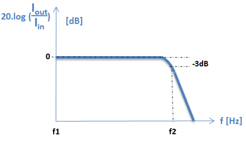
Nominal current cannot be considered over the full frequency range because of magnetic core heating due to core losses. To keep the power dissipation at safe level, RMS current value shall be decreased while working frequency increases. Therefore the frequency bandwidth given in the datasheet is obtained from measurements at currents of low intensity.
-
Why are transducers subject to core losses?
The magnetic material and core design as well as the spectral contents of the current amplitude versus frequency define the level of core losses. They are caused by the enclosed area within the hysteresis cycle, shown on the figure below.
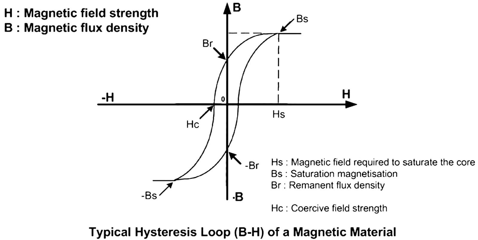
Core losses are combination of eddy current and hysteresis losses.
- The eddy current loss is the power absorbed by a magnetic material due to eddy currents, which are loops of electrical current induced within material by a changing magnetic field, due to Faraday's law of induction. These losses are proportional to the square of the: peak flux density in the core, frequency and lamination sheet thickness of the core.
- The hysteresis loss is the energy loss when the magnetic material is going through a cycling state and is proportional to frequency, core volume and the square of peak flux density.
Core losses become significant at high frequencies and it is essential to limit the current amplitude at these frequencies to acceptable levels (depending on maximum transducer’s temperatures). This implies not only limiting the maximum frequency of the fundamental current, but also harmonic content, since even a low amplitude signal may create unacceptable losses at high frequencies.
-
What is the current derating versus frequency?
Because of the core losses in high frequency applications, the current shall be reduced in order to keep the transducer losses constant. Due to the complexity of the core geometry, the dependence of the core losses with the square of frequency, the square of magnetic flux density and the power dissipation by the housing, it is extremely difficult, if not impossible, to compute or to simulate the RMS current derating versus frequency.
Derating curve of the RMS current versus frequency can be obtained by doing temperature measurements inside the transducer by varying both RMS primary current and the frequency, and ensuring that the maximum authorized temperature is not exceeded.
-
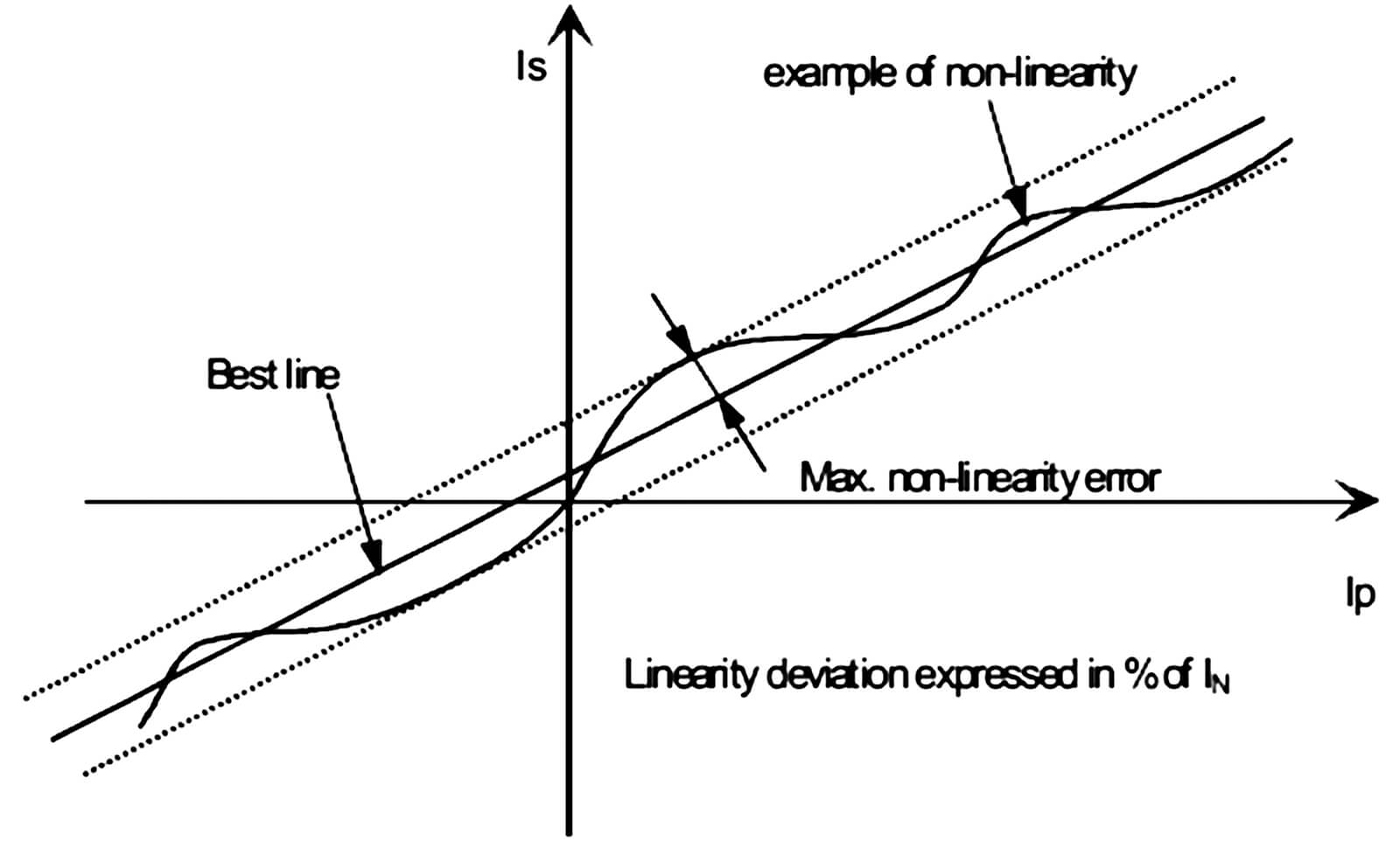
How are sensitivity and linearity measured?
To measure the sensitivity and linearity, the primary current DC is cycled from 0 to IPM then to –IPM and back to 0 .
The sensitivity G is defined as the slope of the linear regression line over the whole current range (the cycle between ±IPM).
The linearity error is the maximum positive or negative difference between the measured points and linear regression line, expressed in percent of the maximum measured value.
-
What are the advantages of transducers using an ASIC?
The ASIC (Application Specific Integrated Circuit) is, as the name indicates, an integrated circuit designed to provide several specific functions in one package.
The advantages are that it offers:
- Improved overall accuracy
- Lower cost
- Smaller size
- Customized functions
- Improved behavior in disturbed environments
- Improved quality level (reliability, aging)
-
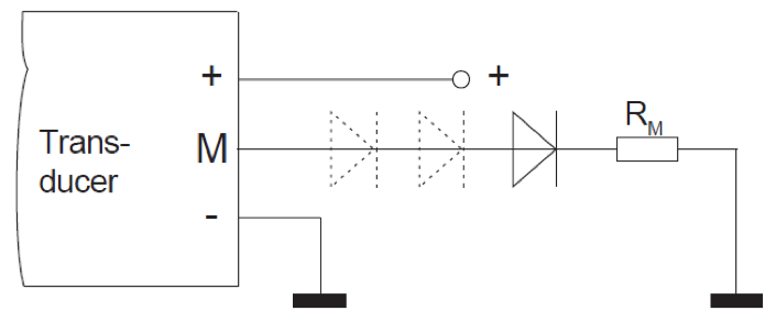
How do transducers with a unipolar power supply work?
The vast majority of LEM closed loop transducers are specified for use with bipolar supply voltages (e.g. ±15 V). However, most transducers can also be operated from an unipolar supply for the measurement of unidirectional currents. In such cases the following must be taken into account (solution is not valid for DV and DVL family):
- The supply voltage should be equal to the sum of the positive and negative voltages indicated in the datasheet (e.g. a ±15 V product should be powered with +30 V).
- Selection of the measurement resistance and the maximum current must not imply excessive power dissipation in the transducer’s output stage (do not hesitate to contact LEM to get the correct measuring resistance assessment).
- The output stage is designed for the use with a bipolar power supply and diodes must be inserted in series with the output to allow a minimum output bias voltage without creating a measurement offset (see the drawing below).
The LEM portfolio also includes some transducers dedicated to unipolar operation and use of these is advised as the electronic design and specifications are based directly on expected operating conditions.
-
How can magnetization of the current transducer be avoided?
Depending on the type of transducer and the magnetic material used, the residual flux (magnetic remanence) of the magnetic core induces an additional measurement offset referred to as ‘magnetic offset’. Its value depends on the previous core magnetization and is at a maximum after the magnetic circuit has been saturated. Magnetization might occur:
- After a high overload current
- Due to the interruption (lack) of power supply
The offset created by the magnetization will disappear:
- Naturally, over a certain period of time depending on the magnetic material that will slowly recover (this is a very slow process).
- By performing a demagnetization of the transducer, either by appropriate reversal of the primary current or a dedicated degauss cycle. Thanks to this process transducer can recover its initial performances.
-
Can a transducer be demagnetized?
The elimination of magnetic offset requires demagnetization. A degauss cycle requires driving the core through the entire B-H loop with a low frequency AC source, then gradually decreasing the excitation returning the B-H operating point to the origin. As a minimum, provide 5 cycles at full amplitude and then decrease the excitation smoothly no faster than 4 % per cycle, requiring 30 cycles or 500 ms at 60 Hz.
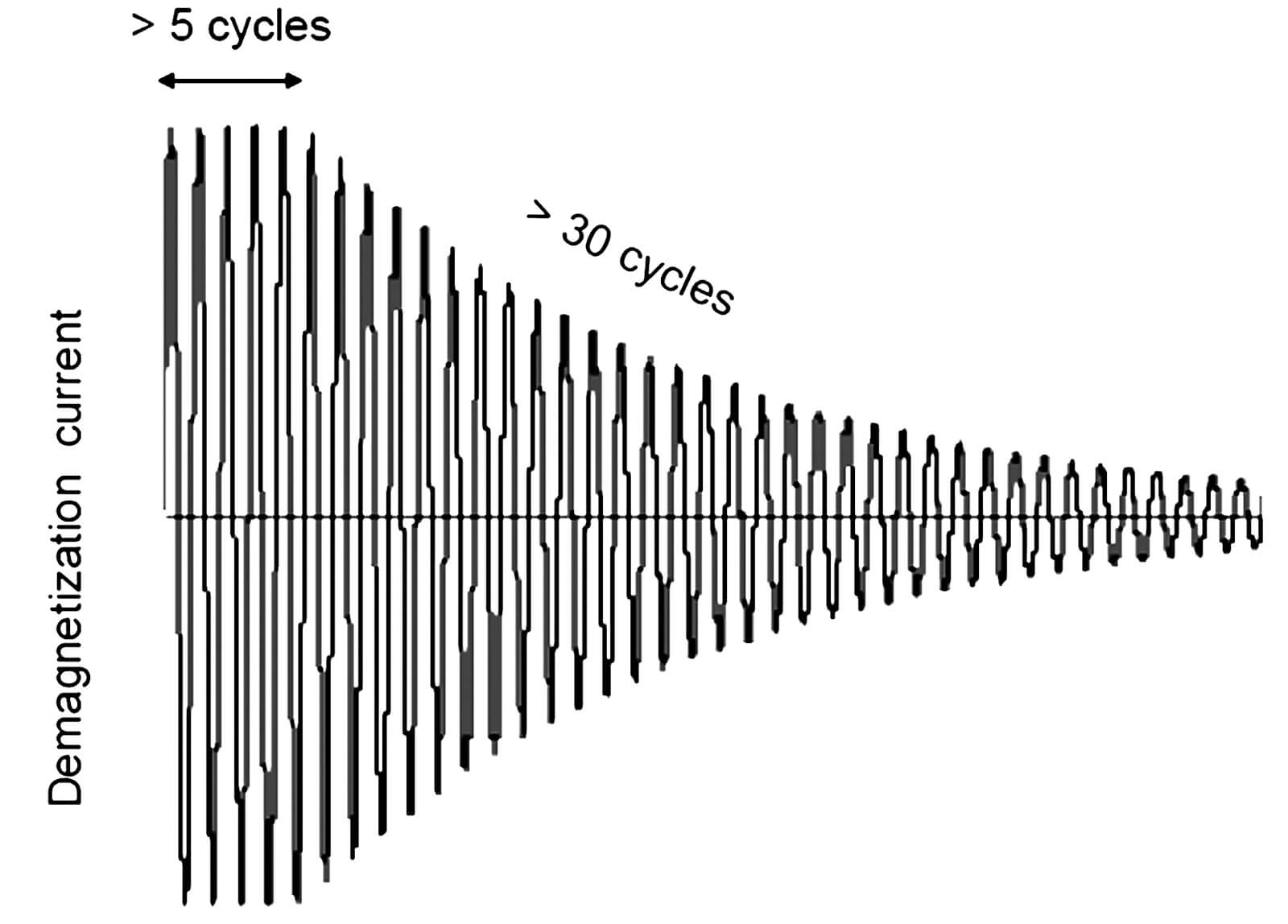
For closed-loop devices, additional care must be taken to ensure the compensation coil does not negate the demagnetization effect. Alternatively, a partial demagnetization of the core is possible by providing an appropriate signal in the opposite polarity of the magnetization. The difficulty is determining the exact amplitude and duration to obtain a satisfactory result. With a well-defined application it may be feasible to determine the required value empirically and apply this correction as necessary.
-
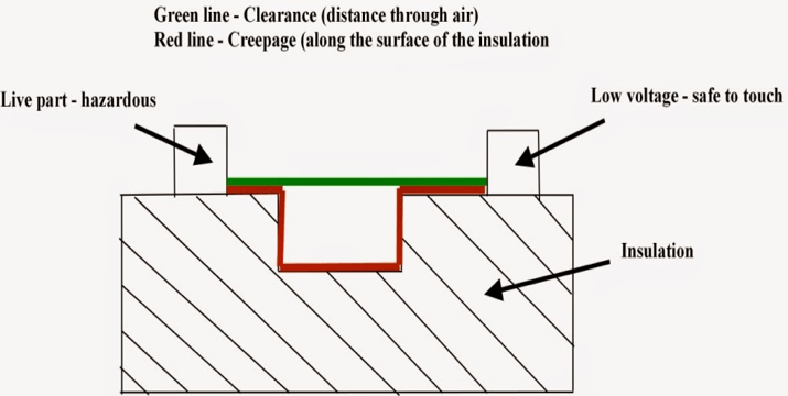
What are clearance and creepage distances?
Several international standards specify safety requirements applicable to the equipment included in their scope, with the main purpose to ensure that hazards to the operator, with respect to electrical, thermal and energy safety considerations are reduced to a tolerable level.
Customer’s application will define necessary voltage level (rated voltage, over-voltage category), safety level (functional, basic or reinforced insulation) and environmental conditions (pollution degree) whereas transducer’s design should insure safe use thanks to the choice of the insulating material (CTI) and the respect of minimum insulation distances.
Safety standards specify the requirements for clearances, creepage distances and solid insulation for equipment based upon their performance criteria. They also include methods of electric testing with respect to insulation coordination.
- Clearance dCl is the shortest distance in air between two conductive parts.
It shall be dimensioned to withstand the required impulse withstand voltage.
For operations beyond an altitude of 2000m above sea level, clearance should be multiplied by the correction factor in order to insure withstand voltage level.
- Creepage distance dCp is the shortest distance along the surface of a solid insulating material between two conductive parts.
It shall be dimensioned to avoid failure due to tracking along the surface of insulation, and take into account:- the pollution degree of the application system
- the CTI of the insulating material
Creepage distance needs to be greater or equal to the clearance.
- Clearance dCl is the shortest distance in air between two conductive parts.
-
What are partial discharge phenomenona explained?
A partial discharge is an electric discharge which occurs in a portion of an insulated area often in voids.
As a consequence of high temperature and emission of ultraviolet radiation generated by small electric arcs in the voids, the insulation layer is degraded. Gradually, small cavities increase and arcs begin to develop inside these cavities. The final step is a complete breakdown between the primary and the secondary parts of the transducer.
If the growth of degraded insulation portions can take several years, the final step takes lasts only one or several electrical periods.
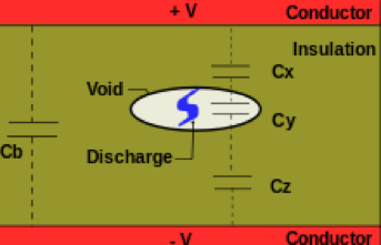
The aim of the partial discharge test is to ensure a long lifetime of LEM transducers. It ensures that the solid insulation (potting + housing) withstands a high voltage stress in the long run:
- recurring peak voltage
- highest steady-state voltage
- long-term temporary overvoltage
On LEM data sheets, we either indicate the value of the partial discharge extinction voltage Ue at 10pC level (older datasheets) or the partial discharge test voltage Ut (recent products).
Results of the test strongly depend on the shape of the busbar (primary conductor) and its position in the transducer aperture.
- We advise to avoid angles and sharp shapes (otherwise risk of corona discharge can appear)
- Busbar has to be centered in the aperture
- Dimensions of the busbar:
- By default, test at LEM is done with the busbar filling the aperture (contact with inner tubing) which is the worst possible case.
- Specific busbar dimensions might be requested from the customer: Busbar dimension and position must be specified with Ut value.
Applications


新着情報
証明書
| Description | LEM entities | |
|---|---|---|
ISO IEC 17025 - Calibration (French) |
LEM Switzerland SA (Switzerland) | |
ISO 14001 |
LEM Switzerland SA (Switzerland) | |
IATF 16949 (LEM International) |
LEM Switzerland SA (Switzerland) | |
5 year warranty certificate |
LEM Switzerland SA (Switzerland) | |
ISO TS 22163 (IRIS) |
LEM Switzerland SA (Switzerland) | |
ISO IEC 17025 - Tests (English) |
LEM Switzerland SA (Switzerland) | |
ISO IEC 17025 - Calibration (English) |
LEM Switzerland SA (Switzerland) | |
ISO 9001 |
LEM Switzerland SA (Switzerland) | |
ISO IEC 17025 - Tests (French) |
LEM Switzerland SA (Switzerland) | |
Tisax Assessment |
LEM Switzerland SA (Switzerland) |